- Compatible with standard Universal, 3.3V or 5V PCI slot
- Industrial temperature operating range (-40°C to +85°C)
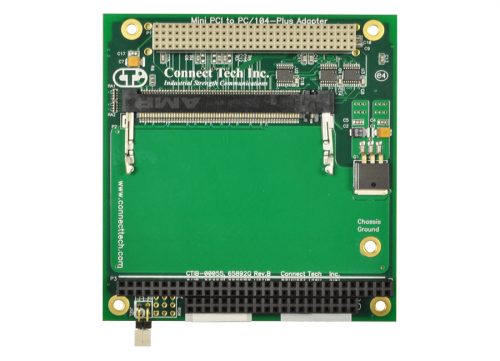
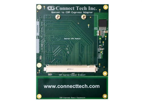
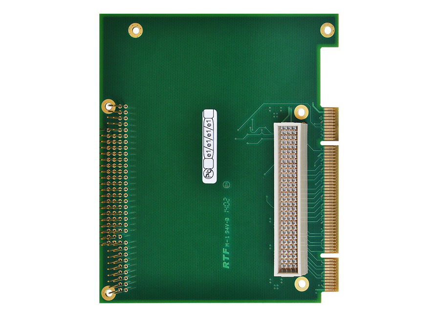
- Connectors/Interfaces include a PCI-104 120 pin stack-through connector with shroud for connection to the host CPU board and PC/104 64 and 40 pin passive stack-through connectors (model AD001)
- Measures 4.913″ wide by 4.200″ high
- +5V input for PCIe/104 add-in card
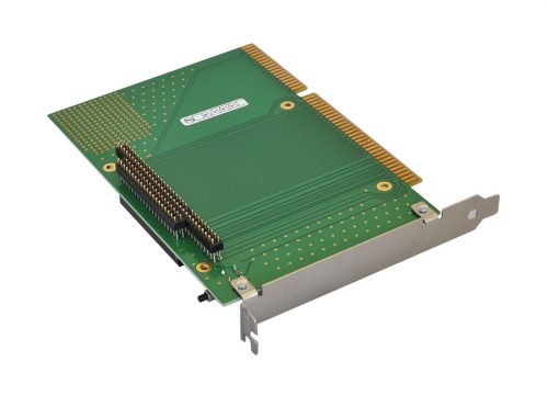
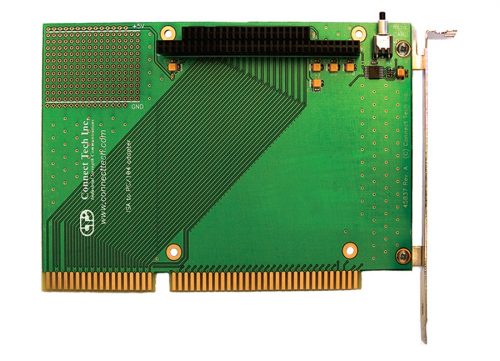
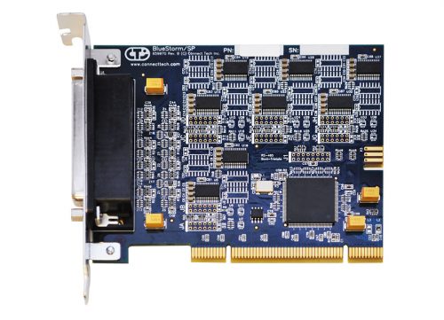
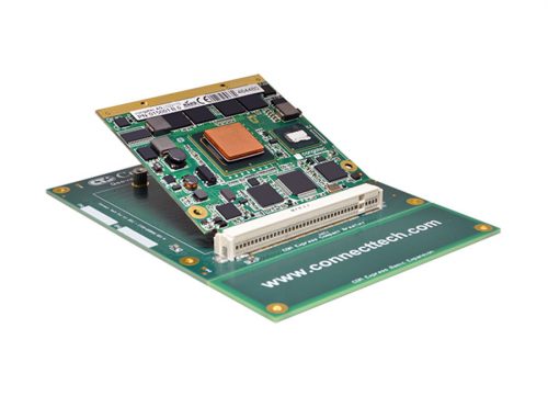
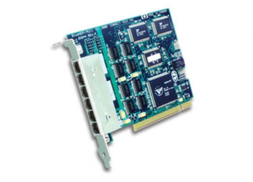
PCI to PC/104-Plus Adapter
More Information
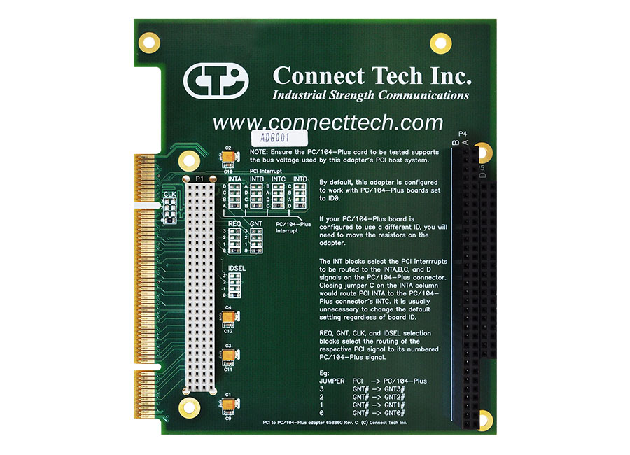
This passive extender card allows developers to mount a PCI-104 or PC/104-Plus card into a Universal PCI bus system. The adapter is equipped with a stack-through connector so the test card can be installed on either side (model ADG001), enabling probing on the front or the back. The design also allows cables to exit from the host PC for easy connection to external devices.
Specifications
| Operating Temperature | -40°C to +85°C (-40°F to +185°F) |
|---|---|
| Dimensions | 4.913“ wide by 4.200” high |
Usage
Standard Usage
Insert the adapter into the desired slot in your host system. Connect the test PC/104-Plus card into the connector. It is recommended you use the adapter in its default configuration. To do so, configure the PC/104-Plus test card for ID0. No additional configuration is required.
Important Notes:
Only one PC/104-Plus card can be used per adapter card.
Ensure the PC/104-Plus card under test supports the bus voltage used by the adapter’s PCI host system. Consult your system documentation to determine the voltage on your PCI connector.
Special Usage
You may have a situation in which you cannot set the test card to ID0, the default configuration of the PCI to PC/104-Plus adapter. In this rare case, you will need the following information to configure the adapter to apply to your particular setup.
REQ, GNT, CLK and IDSEL selection
To ensure each card within a PC/104-Plus stack has a unique set of signals (REQx, GNTx, CLKx and IDSELx) multiple copies of these signals exist in the PC/104-Plus bus, numbered 0 to 3. The REQ, GNT, CLK and IDSEL jumper blocks will route the PCI signal to the equivalent PC/104-Plus signal. If your test card is configured to use a different ID, then you need to move the resistors on the adapter to coincide with that ID. If your PC/104 card is set to ID3, for example, move the resistors in the REQ, GNT, CLK and IDSEL locations on the face of the card to the row numbered 3 to connect the signals to your test card.
Interrupt selection
The default configuration is sufficient in most cases and routes the PCI INTA, B, C and D interrupt lines to the INTA, B, C and D lines on the PC/104-Plus card. If need be, you can select which PCI interrupts are routed to the PCI-104 or PC/104-Plus interrupt lines via the INTx blocks. To change the default selection, jumper the corresponding PCI interrupts to route to the INTA, B, C and D signals on the PC/104-Plus connector. For example, jumper the adapter’s INTA C position to route INTA to the PC/104-Plus card’s INTC. (It is recommended you route unique interrupts to each of the PC/104-Plus interrupt lines.)
Ordering Information
| Main Products | |
|---|---|
| Part Number | Description |
| ADG001 | PCI to PC/104-Plus Adapter |
Custom Design
Looking for a customized Development Tool or Adapter? Click here to tell us what you need.